BACnet is a registered trademark of ASHRAE. ASHRAE does not endorse, approve or test products for compliance with ASHRAE standards. Compliance of listed products to the requirements of ASHRAE Standard 135 is the responsibility of BACnet International. The BTL logo is a registered trademark of BACnet International.
BACnet and Modbus are available only on series HTN104.
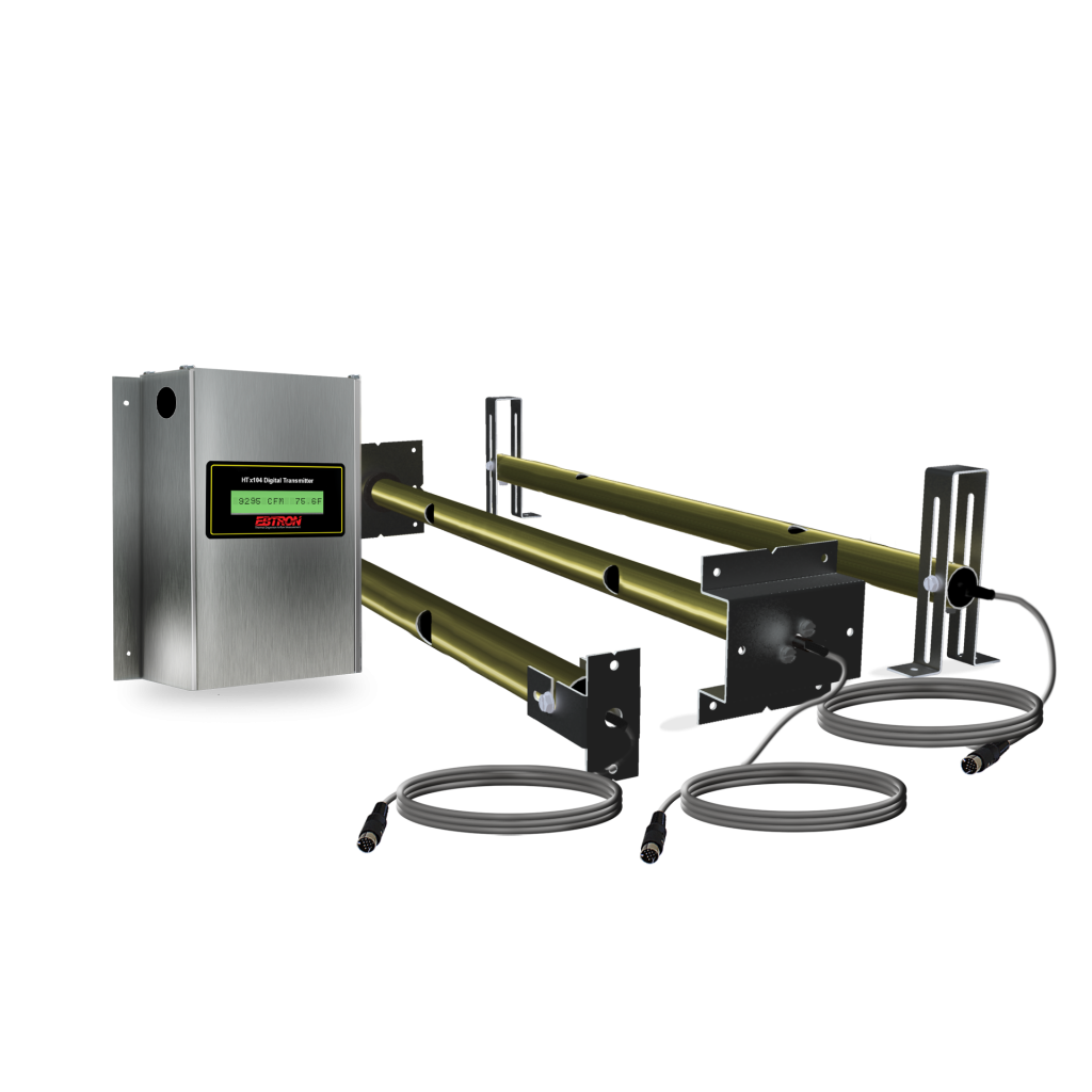
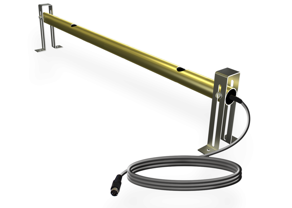
The HTx104-PE is EBTRON’s most economical solution for larger systems when “out-of-the-box” installed accuracy is not required and field adjustment is acceptable. Perfect for LEED outdoor air delivery monitoring or other low sensor density airflow measurement applications.
Probe and Sensor Node Configurations (max.)
1 probe x 4 sensor nodes/probe
2 probes x 2 sensor nodes/probe
Installed Airflow Accuracy¹
≤ 2 sq.ft. [0.185 sq.m.]: [0.18 sq.m]: ±3% of reading
> 2 sq.ft. [0.185 sq.m.]: ±(3% to 10%), typical (increases with increasing duct size). May be improved by field adjustment using the Field Adjust Wizard (FAW) to a reliable reference.
Sensor Density
Refer to the PC sensor density table.
Sensor Node Averaging Method
Airflow: Independent, arithmetic average
Temperature: Independent, velocity weighted average
Listings and Compliance
UL: UL 873 Listed CSA C22.2 No. 24
CE: European shipments only
UKCA: UK shipments only
BACnet International: BTL Listed (HTN104 transmitter)
FCC: This device complies with Part 15 of the FCC rules
RoHS: This device is RoHS2 compliant
Environmental Limits
Temperature:
Probes: -20 to 160 ⁰F [-28.9 to 71.1 ⁰C]Transmitter: -20 to 120 ⁰F [-28.9 to 48.9 C]
Humidity: (non-condensing)
Probes: 0 to 100%
Transmitter: 5 to 95%
Sensing Node Sensors
Self-heated sensor: Precision, hermetically sealed, bead-in-glass thermistor probe
Temperature sensor: Precision, hermetically sealed, bead-in-glass thermistor probe
Sensing Node Housing
Material: Glass-filled Polypropylene (Kynar® with /SS option)
Sensor Potting Materials: Waterproof marine epoxy
Sensing Node Internal Wiring
Type: Kynar® coated copper
Airflow Measurement
Accuracy: ±2% of reading to NIST-traceable airflow standards (includes transmitter uncertainty)
Calibrated Range: 0 to 5,000 fpm [0 to 25.4 m/s]Calibration Points: 16
Temperature Measurement
Accuracy: ±0.15 ⁰F [0.08 ⁰C] to NIST-traceable temperature standards (includes transmitter uncertainty)
Calibrated Range: -20 to 160 ⁰F [-28.9 to 71.1 ⁰C]Calibration Points: 3
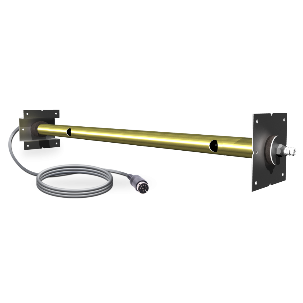
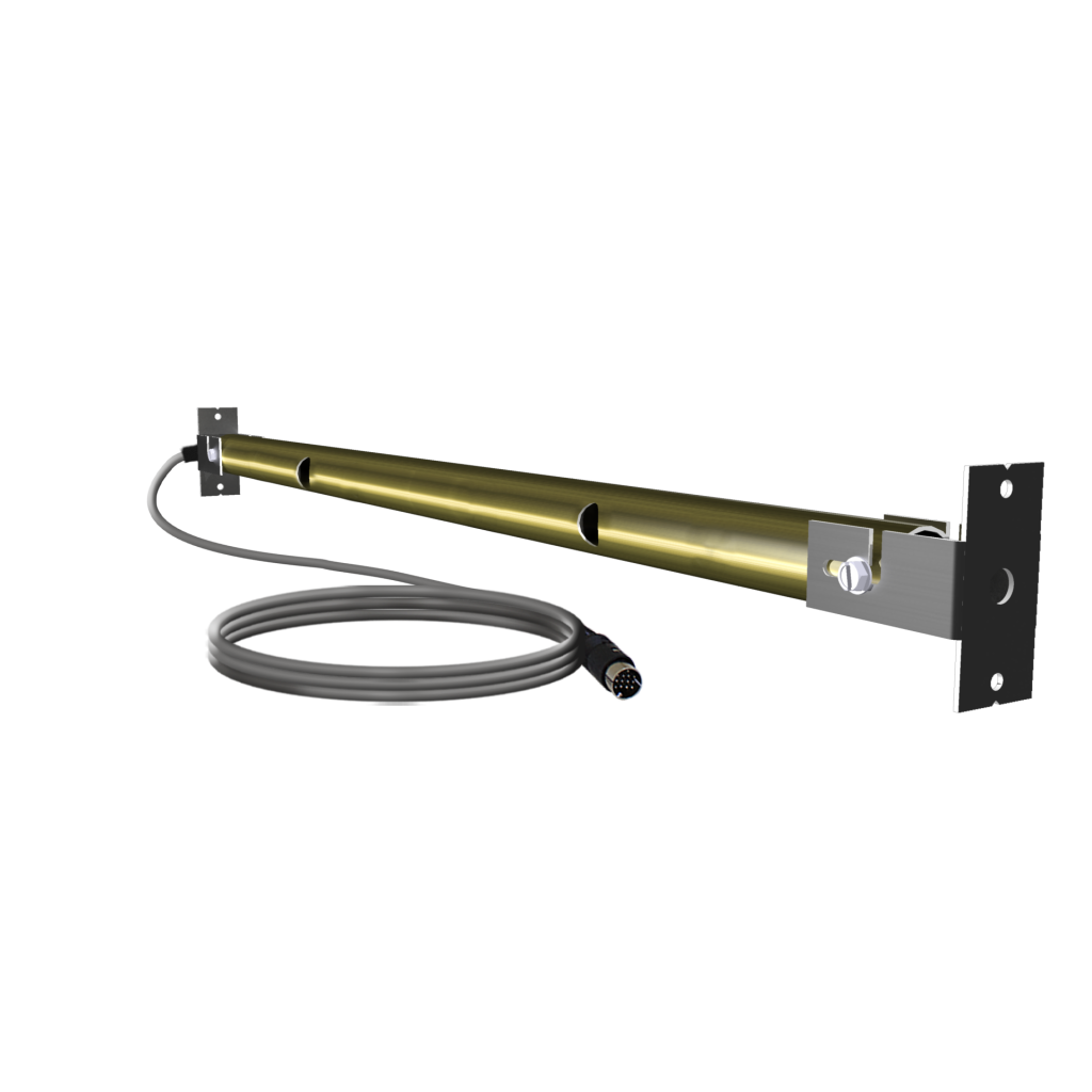
Tube
Material: Gold anodized 6063 aluminum (316 stainless steel with /SS option)
Mounting Brackets
Material: 304 stainless steel
Options & Standard Size Limits2
Insertion: 6 to 191 in. [152.4 to 4851 mm]Stand-off: 6 to 190 in. [152.4 to 4826 mm]Internal: 8 to 194 in. [203.2 to 4928 mm]
Probe to Transmitter Cables
Type: FEP jacket, plenum rated CMP/CL2P, UL/cUL listed, -67 to 302 ⁰F [-55 to 150 ⁰C], UV tolerant
Standard Lengths: 10, 15, 20, 25, 30, 40 and 50 ft. [3.1, 4.6, 6.1, 7.6, 9.1, 12.2 and 15.2 m]Connecting Plug: 0.60” [15.24 mm] circular DIN
Power Requirement:
24 VAC (22.8 to 26.4 under load) @11V-A
PCB Connections:
Gold-plated PCB interconnects and test points
User Interface:
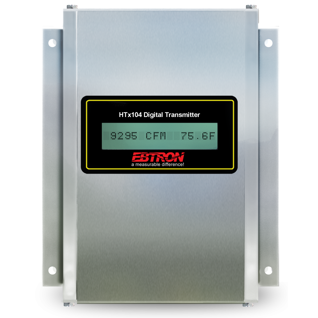
16-character LCD display and 4 button interface
B.A.S. Connectivity Options
HTA104 Transmitter: Two field selectable (0-5/0-10 VDC or 4-20mA), scalable and isolated analog output signals (AO1=airflow, AO2=temperature or alarm)
HTN104 Transmitter: One field selectable (BACnet MS/TP or Modbus RTU) and isolated RS-485 network connection- Individual sensor node airflow rates and temperatures are available via the network
Airflow Alarm
Type: Low and/or high user defined setpoint alarm
Tolerance: User defined % of setpoint
Delay: User defined
Zero Disable: Alarm can be disabled when the airflow rate falls below the low limit cutoff value (unoccupied periods)
Reset Method: Manual or automatic
Visual Indication: Yes, LCD display
Network Indication: Yes (HTN104 only)
Analog Signal Indication: Yes, on AO2 assignment (HTA104 only)
System Status Alarm
Type: Sensor diagnostic system trouble indication
Visual Indication: Yes, LCD display
Network Indication: Yes (HTN104 only)
Analog Signal Indication: Yes, on AO2 assignment (HTA104 only)
¹Installed airflow accuracy allows for additional uncertainty that results from averaging a finite number of sensors in a contorted velocity profile created from up and downstream disturbances. The specified installed accuracy is based on the PE sensor density rules for installations that meet or exceed EBTRON minimum placement requirements. PE sensor density rules may not be available for all duct sizes due to sensor placement limitations (see PE sensor density tables for more information).

© 2023, EBTRON, Inc.
