BTL and Modbus are available only on GTB108e, GTM108e, and GTC108e.
BACnet is a registered trademark of ASHRAE. ASHRAE does not endorse, approve, or test products for compliance with ASHRAE standards. Compliance of listed products to the requirements of ASHRAE Standard 135 is the responsibility of BACnet International. The BTL logo is a registered trademark of BACnet International.
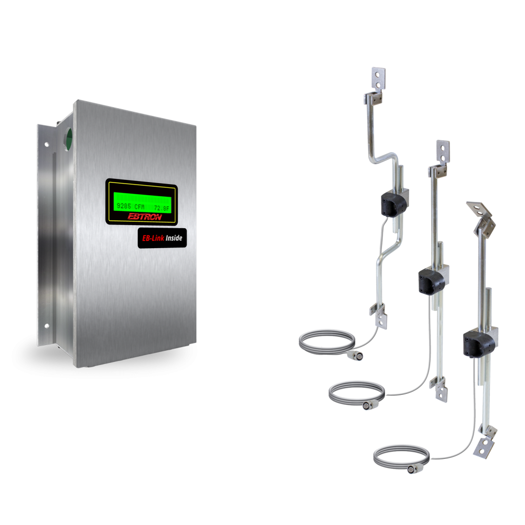
The GTx108e-F/An is an accurate and repeatable airflow and temperature measurement system in fan arrays that support one to eight fans. Individual airflow rates and fan alarming are available with combination analog output/network models. The system does not affect fan performance. EB-Link App is a tool that can enhance commissioning or provide a quick validation anytime without going through the BAS—data at the Touch of Your Finger.
Probe and Sensor Node Configurations
Fan Arrays (less than or equal to 4 fans): 2 probes x 1 sensor node per probe or 1 probe x 1 sensor node per probe in each fan
Fan Arrays (greater than 4 fans): 1 probe x 1 sensor node per probe in each fan (8 probe maximum)
Installed Airflow Accuracy¹
±(3% to 10%) of reading, depending on fan type and installation. May be improved by field adjustment using the Field Adjust Wizard (FAW) to a reliable reference.
Sensor Node Averaging Method
Airflow: Independent, arithmetic average per fan
Temperature: Independent, velocity weighted average
Listings and Compliance
UL: UL-873 and CSA C22.2 No. 24
CE: European shipments only (EB-Link not available)
UKCA: UK shipments only
BACnet International: BTL Listed (GTC108 and GTM108 transmitters)
FCC:This device complies with Part 15 of the FCC rules
RoHS:This device is RoHS2 compliant
Environmental Limits
Temperature:
Probes: -20 to 160 ⁰F [-28.9 to 71.1 ⁰C]Transmitter: -20 to 120 ⁰F [-28.9 to 48.9 ⁰C]Humidity: (non-condensing)
Probes: 0 to 100%
Transmitter: 5 to 95%
Mounting Rods
Material: Zinc plated steel
Mounting Brackets
Material: 304 stainless steel
Mounting Options & Size Limits
Forward: 6 to 64 inches [152.4 to 1676.4 mm] (diameter at inlet entrance)
Face: 11 to 77 inches [152.4 to 1625.6 mm] (diameter at inlet entrance)
Flare: 6 to 57 inches [279.4 to 1955.8 mm] (opening size at backdraft damper inlet)
Probe to Transmitter Cables
Type: FEP jacket, plenum rated CMP/CL2P, UL/cUL listed, -67 to 302 ⁰F [-55 to 150 ⁰C], UV tolerant
Standard Lengths: 10, 25, and 50 ft. [3.1, 7.6 and 15.2 m]Connecting Plug: 9/16” [14.29 mm] nominal diameter
Power Requirement
24 VAC (22.8 to 26.4 under load) @16V-A
PCB Connections:
PCB interconnects, PCB edge fingers, and test points
User Interface
2 line x16-character backlit LCD display and 4 button interface
B.A.S. Connectivity Options
All Transmitter: Three field selectable (0-5/0-10 VDC or 4-20mA), scalable and isolated analog output signals (AO1=airflow, AO2=temperature or alarm, AO3=Not used.
GTA108e Transmitter: No additional connectivity to B.A.S.
GTC108e Transmitter: One additional field selectable (BACnet MS/TP or Modbus RTU) and isolated RS-485 network connection -Individual sensor node airflow rates and temperatures are available via the network.
GTB108e Transmitter: One additional field selectable (BACnet MS/TP or Modbus RTU) and isolated RS-485 network connection and one additional isolated Ethernet (simultaneously supported BACnet Ethernet or BACnet IP, Modbus TCP and TCP/IP) network connection – Individual sensor node airflow rates and temperatures are available via the network.
GTM108e Transmitter: One additional isolated Ethernet (simultaneously supported BACnet Ethernet or BACnet IP, Modbus TCP and TCP/IP) network connection – Individual sensor node airflow rates and temperatures are available via the network.
GTF108e Transmitter: One additional isolated Lonworks Free Topology network connection.
GTU108e Transmitter: One additional USB connection for thumb drive data-logging of sensor node airflow rates and temperatures.
Airflow Alarm
Type: Low and/or high user defined setpoint alarm
Tolerance: User defined % of setpoint
Delay: User defined
Zero Disable: Alarm can be disabled when the airflow rate falls below the low limit cutoff value (unoccupied periods)
Reset Method: Manual or automatic
Visual Indication: Yes, LCD display
Network Indication: Yes (GTM108 and GTC108 only)
Analog Signal Indication: Yes, on AO2 assignment
Fan Alarm
Type: Minimum airflow, % deviation from median airflow, or % deviation from maximum airflow stored in memory
Tolerance: User defined % of setpoint
Delay: User defined
Zero Disable: Alarm can be disabled when the airflow rate falls below the low limit cutoff value (unoccupied periods)
Reset Method: Manual or automatic
Visual Indication: Yes, LCD display
Network Indication: Yes (GTM108 and GTC108 only)
Analog Signal Indication: Yes, on AO2 assignment
System Status Alarm
Type: Sensor diagnostic system trouble indication
Visual Indication: Yes, LCD display
Network Indication: Yes
Analog Signal Indication: Yes, on AO2 assignment
EB-Link Bluetooth Interface for Android® and iPhone®
Download individual sensor node airflow/temperature data, settings and diagnostic.

© 2023, EBTRON, Inc.
